BLAze - Bearing Lubrication Automation Work Cell
This was a really involved project that had a bit of everything. The work cell was built
around a Denso SCARA robot that did the complex job of precisely lubricating high precision
ball bearings. For reference, normal bearing would be wholesaled for around a dollar while
some of these bearings would wholesale for $100 each. Tolerances were really tight. So tight
that dispensing had to be checked and calibrated every 10 bearings. Needle placement and
height had to be precise to 0.1mm. Since glass trays we used had glass thickness variance
of up to 0.4mm the glass height had to be detected every few inches. In addition to these
tolerances the system had to be very robust to handle a wide variety of bearings.
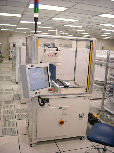 Unit Installed in Customer Cleanroom
My Role
My role was as the owner of the company, Service Machines Inc.,
charged with designing, and building the unit for a manufacturing client. I supervised the team of 4-5 engineers working on the
project. I also did a fair bit of hands on work on the project including the touchscreen interface
application.
Machine Vision
The system used two cameras. One was used to find the position of each bearing in a tray of bearings.
The other was aimed at a grease dispensing fixture designed to detect bubbles to keep them from
undermining the dispensing accuracy.
The software for the machine vision was custom made to the specific needs of the task. Off the shelf
software detected too many false positives. A simple algorithm was used to detect bearings given a
known bearing size. Using various points picked based on the size of the bearing, go left, right, top, bottom till
a bearing wall is detected and use those points to calculate the center. Although it is based on a
really simple idea, it produced rock solid results. Equally important were lots of checks put in place
to ensure against false positives and double counting.
One interesting aspect of the machine vision was that it had to correct for inaccuracies in the SCARA
Robot movement. The SCARA Robot, though very accurate in terms of repeatability, was not very accurate
in moving in a the X-Y plane. In tests we did with a pen put on the end of the robot, which was then
instructed to move in straight lines, the lines it drew were arced one way or another. To correct for this we used
relative positioning from the location of the robot at the time an image was taken. By retaking images
every few inches or so, we were able to get 0.1mm robot positioning accuracy across the entire work
area. The people at Denso had not heard of this level of non-repeating accuracy at the time.
Detecting Bearing ID and OD
Detecting Bearings that Fit Size Criteria
Dispensing
Dispensing refers to extruding grease from a tube. Tolerances of the bearings demanded that
the dispensing had to be calibrated frequently. The dispensing method, required by the
customer, was to use an air valve that was turned on for a given number of milliseconds.
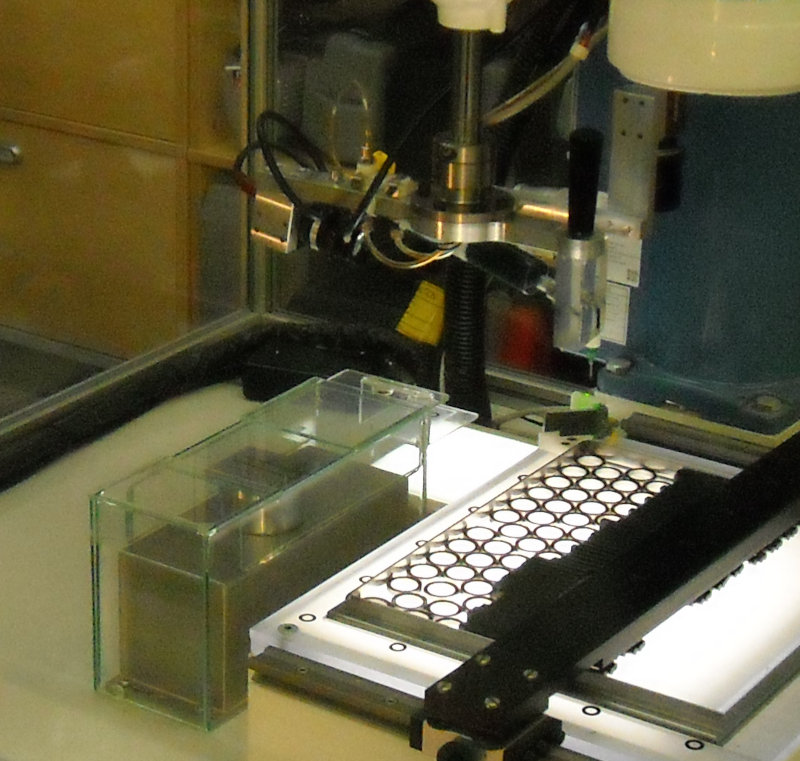
Due to the variable nature of this method a highly sensitive scale, inside a glass box to
minimize the effects of air currents, was used. The robot dispensing head would slide the
box lid open, dispense a line of grease, close the lid, then the system could read the value
from the scale and adjust the number of milliseconds of air pressure used to dispense. This
was done over and over till the readings were consistently within tolerances. This task, so
simple for a human to do, required tons of programming to pull off.
The work process was: Load the bearings, Calibrate dispensing, Lube a few bearings, Calibrate dispensing, Lube a few bearings, etc.
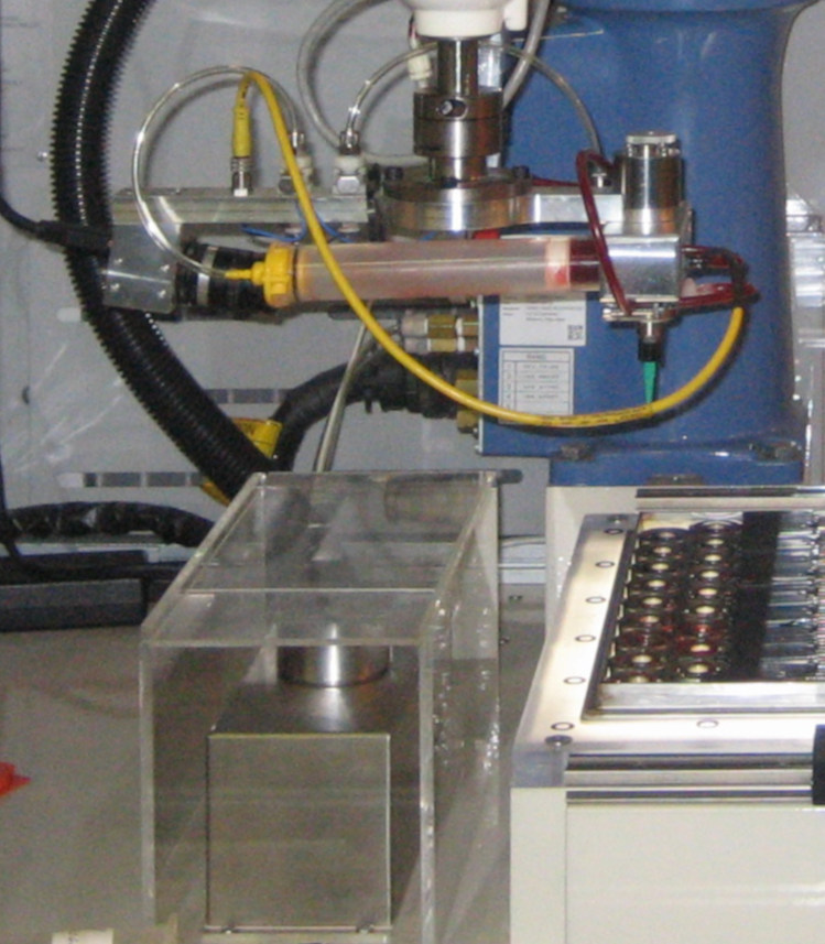 Dispensing Head Under Development
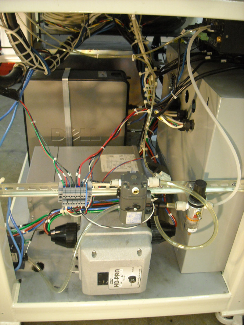
 Dispensing System
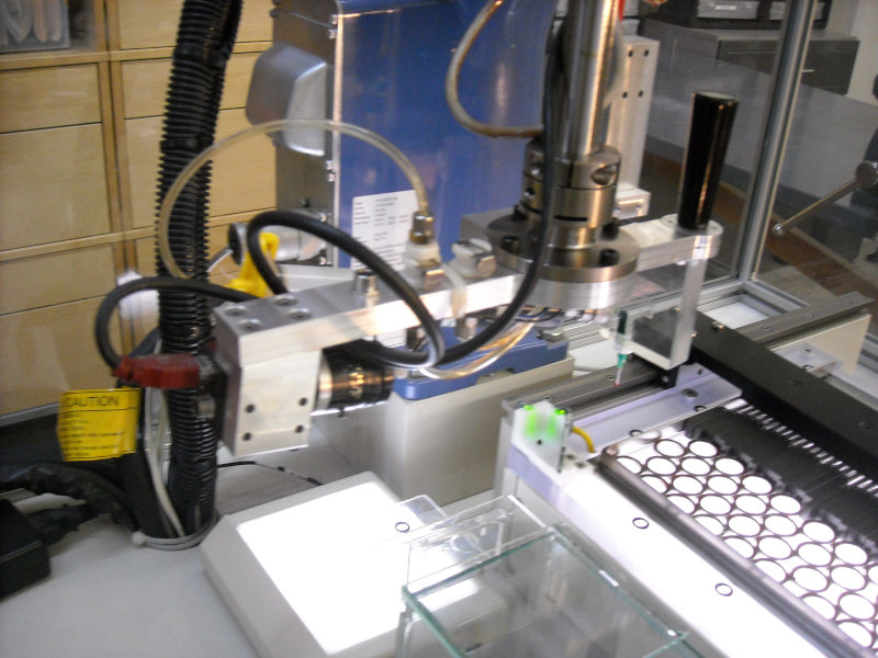 Dispenser Head
SCARA Robot
The Denso SCARA robot was amazing in it's reliability and speed. It came with a PC sized
robot controller box that had it's own programming interface and language. Since most
of the robots movement would be custom to each use, much of the programming was done on
a windows PC overseeing the system. After obtaining an image the PC would calculate robot
movements and send a batch of commands to the controller.
Control Panel
A Windows PC connected touchscreen provided the main interface to operate the system.
From the panel operators could enter job parameters and start the system running.
This interface application was written in C#. There were also buttons on the panel to
start, stop, and emergency stop the machine.
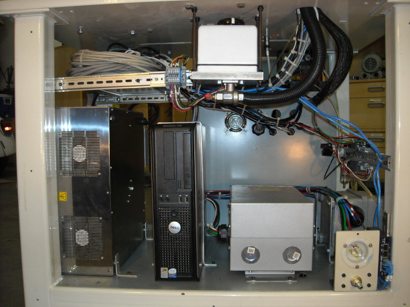
Lots of Parts and Communications
The system had all kinds of parts. For starters the major parts included the case,
robot, light table, scale, grease dispenser, and touch screen. Other parts included
a light curtain, dispensing controller, grease exhaust valve, buttons, switches,
network router, lights, three phase GFI, and a bunch of stuff I can't remember. It was a lot of stuff
to sort out and get right.
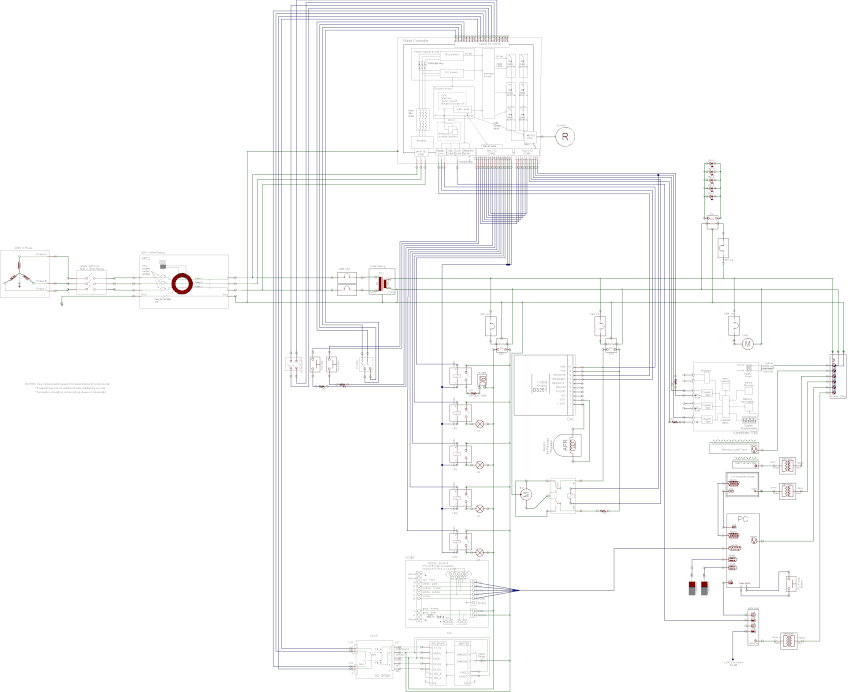 Wiring Diagram
 Front with cover removed
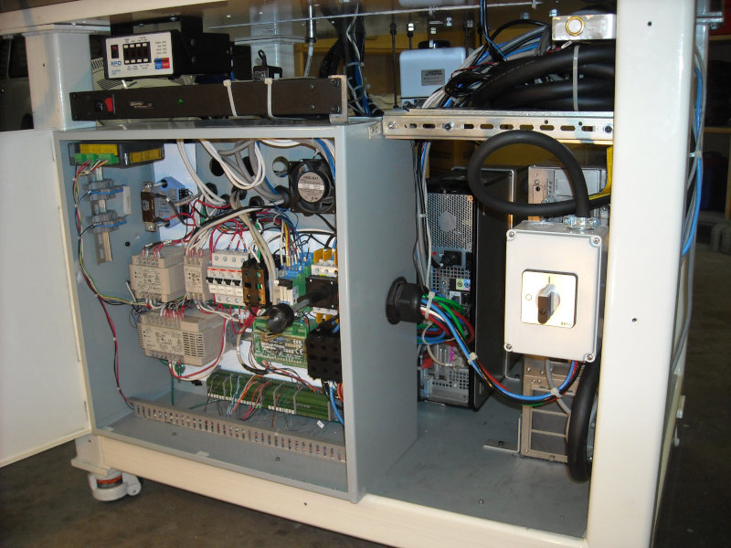
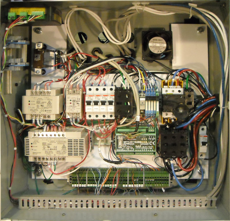 Main Control Box
 Side with Cover Removed
 Back with Cover Removed
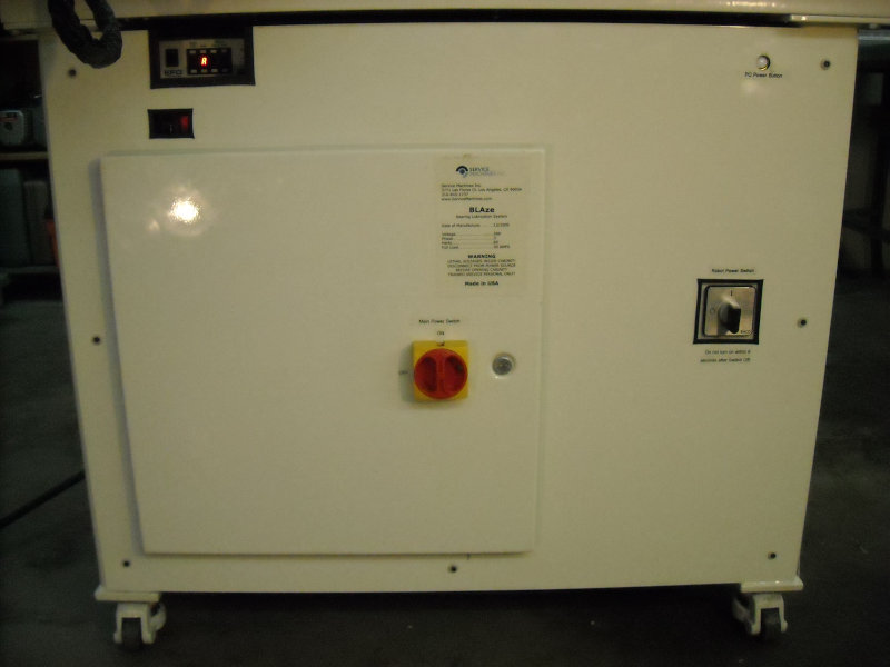
Housing
The housing was totally custom made. It was build around an inch thick steel platform used to absorb
robot movements. The rest of the frame was constructed from various steel parts.
It was welded and powder coated and looked fully professional. The top housing was made
from off the shelf parts including extruded framing components and plexiglass.
 Housing